Recently, our Comcast internet service has been less than ideal. Some strange interference on the cable line is causing our modem to freak out every so often. After talking to countless technicians and service reps and going through 2 or 3 modems trying to determine the problem, I decided to take matters into my own hands.
The main problem was that the modem would freeze after this mysterious event would knock it offline. The only way to re-establish a connection would involve power cycling the modem. This became very annoying when the modem was freezing as often as every 20 minutes at it's worst.
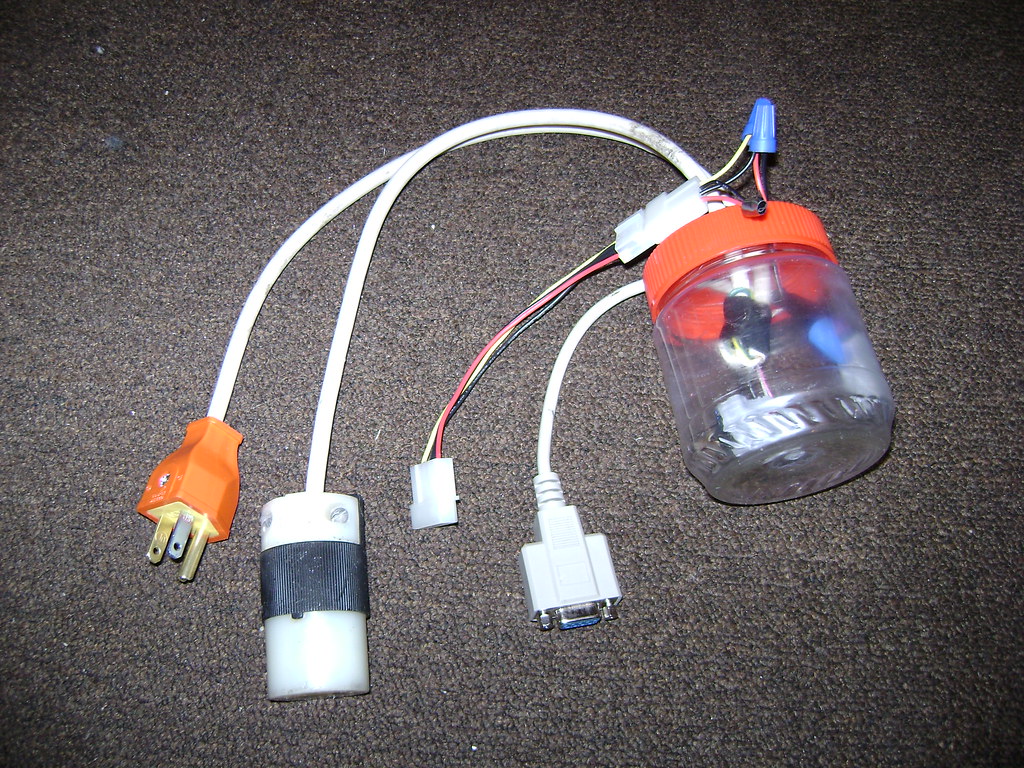
I decided to come up with a solution to replace the task of manually power cycling the modem and to automate it with something aware of internet connectivity. My first thought was to use the RTS pin on a serial port to trigger a relay. I threw together a circuit from parts I had lying around including a transistor, a relay, a female DB-9 connector, and a molex connector (to connect to the PSU of my DD-WRT x86 router for the 12v coil on the relay) and a peanut butter jar for a simple enclosure. This was the end result, which sorta worked (it didn't like long serial extension cables, probably too much voltage drop).
(Original prototype)

After thinking about it for a while, I realized I wanted something more "embedded" and easier to implement (ie, not requiring a PC) and decided to try and use the GPIO pins on a Fonera wireless router. The Fon was a perfect device for the job since it already had a network connection and did not need a whole lot of power to operate 24/7.
The first step was to lookup pinouts for the Fon and determine where the best connection was to an available GPIO pin, power and ground. After some research, this is what I came up with.
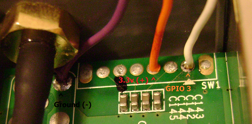
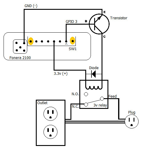
I soldered in some wires and began work on the relay circuit. I used a small NPN transistor connected to the GPIO pin to power the relay (the GPIO itself could not source enough current to trip the coil). Below is the circuit diagram I came up with (after the fact).
(New Schematic, I had the transistor implemented wrong in the original diagram)
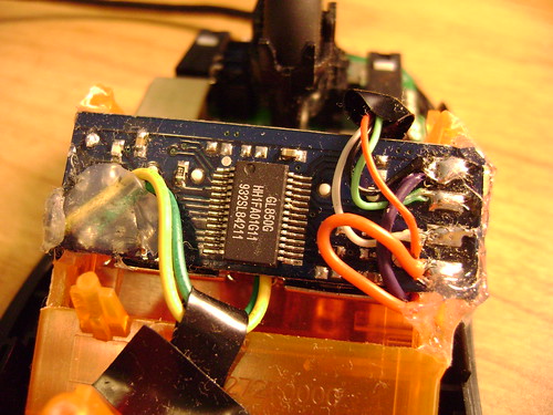
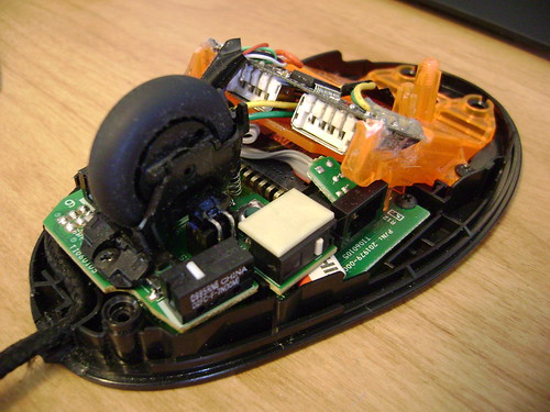
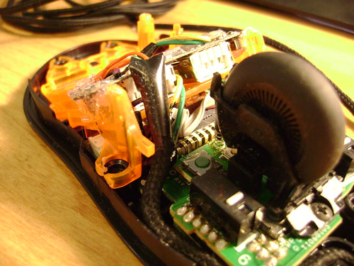
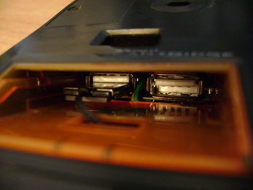
Here is the half of the circuit inside the Fon, with the NPN transistor connected to the GPIO pins

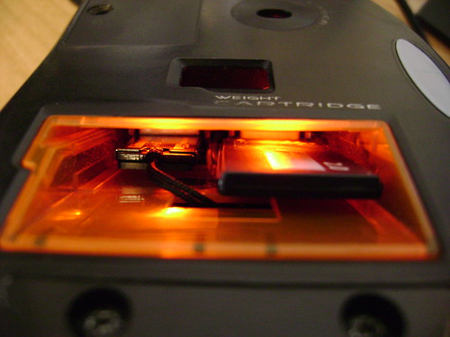
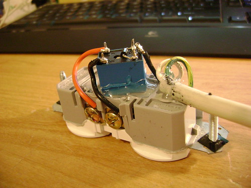
Here is the half of the circuit inside the outlet box, with the relay and a generous amount of hot glue :) (Note: I cut the little metal bridge between the two outlets so that I could have one normally open, and one normally closed)
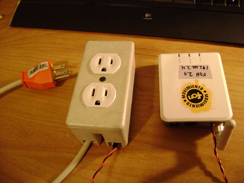
And the finished product!
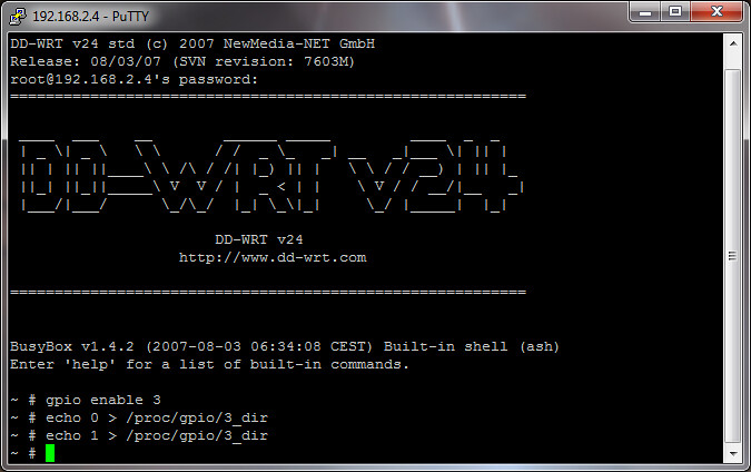
These are the commands I used to turn the GPIO pin on and off
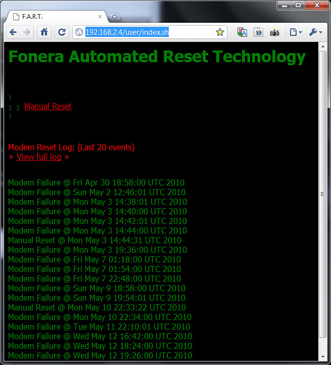
Then, I created a simple web interface with a "Manual reset" button, a short log of the last 20 events, and a link to view the entire log (which got pretty long after a while).
(Click the image for a larger version)

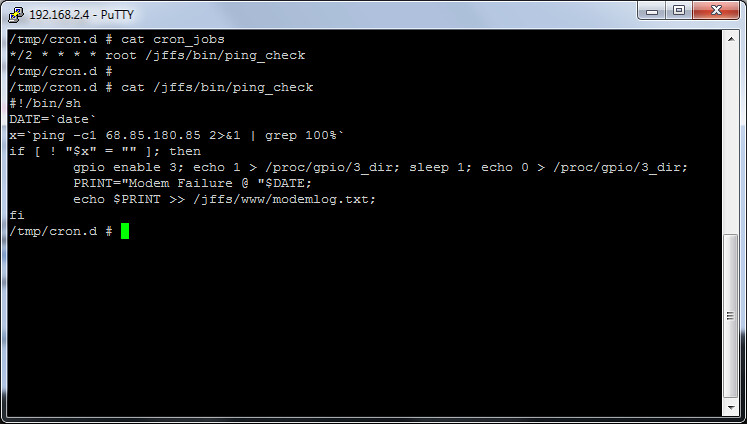
I also created a simple ping script and a cron job which ran every 2 minutes, pinging a comcast gateway (it was the first IP address out side the modem I hit when I ran a trace route)
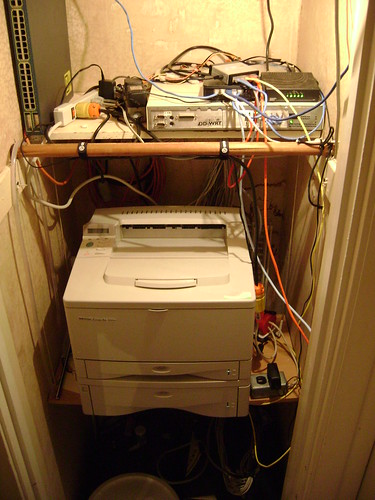
And finally, the finished product in use! (this was an earlier revision, when the relay was still being housed in the peanut butter jar) You can see the Fonera and the outlet box with the modem's wall-wort to the right of the printer.
(Click the image for a larger version)
All in all, this was a very fun project and it seems to do it's job very nicely. The only time we experience any problems now is when the cable line is so noisy that the modem takes more than two minutes to re-sync, and goes through a couple resets before it's good again.
I hope this information can help someone else build a similar device to fix a similar problem (I know there are lots of frustrated comcast customers out there that this project might help). If you come across something in my write up that doesn't make sense, or needs clarification, leave a comment or otherwise contact me and I'll try to help you out as best I can.
Happy Hacking!