The main problem was that the modem would freeze after this mysterious event would knock it offline. The only way to re-establish a connection would involve power cycling the modem. This became very annoying when the modem was freezing as often as every 20 minutes at it's worst.
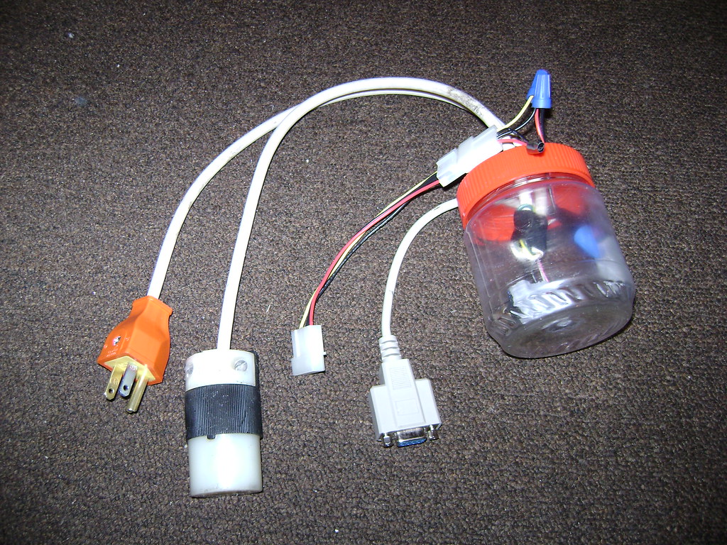
I decided to come up with a solution to replace the task of manually power cycling the modem and to automate it with something aware of internet connectivity. My first thought was to use the RTS pin on a serial port to trigger a relay. I threw together a circuit from parts I had lying around including a transistor, a relay, a female DB-9 connector, and a molex connector (to connect to the PSU of my DD-WRT x86 router for the 12v coil on the relay) and a peanut butter jar for a simple enclosure. This was the end result, which sorta worked (it didn't like long serial extension cables, probably too much voltage drop).
(Original prototype)
After thinking about it for a while, I realized I wanted something more "embedded" and easier to implement (ie, not requiring a PC) and decided to try and use the GPIO pins on a Fonera wireless router. The Fon was a perfect device for the job since it already had a network connection and did not need a whole lot of power to operate 24/7.
The first step was to lookup pinouts for the Fon and determine where the best connection was to an available GPIO pin, power and ground. After some research, this is what I came up with.
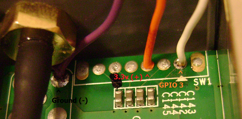
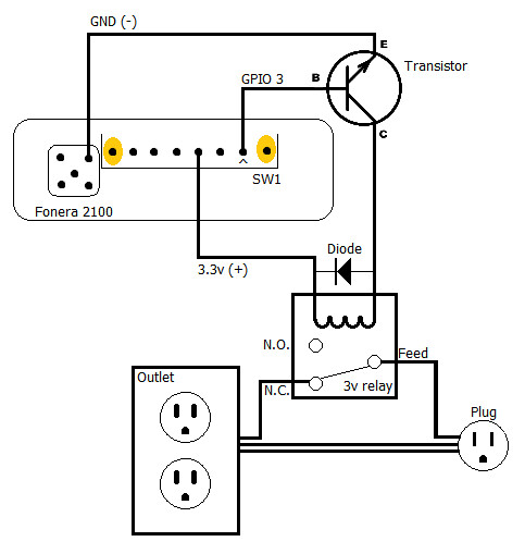
I soldered in some wires and began work on the relay circuit. I used a small NPN transistor connected to the GPIO pin to power the relay (the GPIO itself could not source enough current to trip the coil). Below is the circuit diagram I came up with (after the fact).
(New Schematic, I had the transistor implemented wrong in the original diagram)
Here is the half of the circuit inside the Fon, with the NPN transistor connected to the GPIO pins

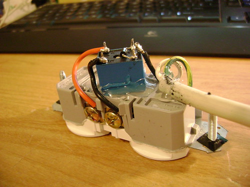
Here is the half of the circuit inside the outlet box, with the relay and a generous amount of hot glue :) (Note: I cut the little metal bridge between the two outlets so that I could have one normally open, and one normally closed)
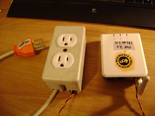
And the finished product!
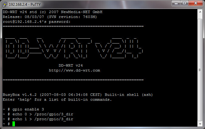
These are the commands I used to turn the GPIO pin on and off
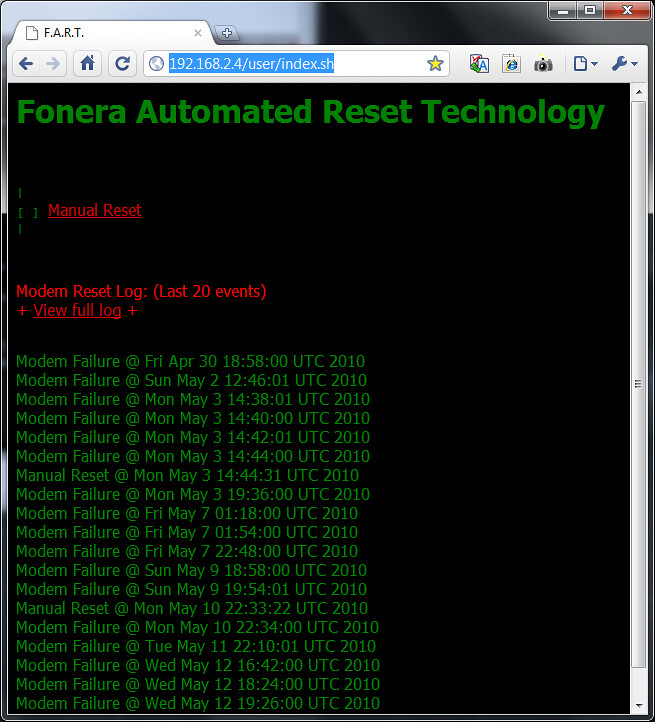
Then, I created a simple web interface with a "Manual reset" button, a short log of the last 20 events, and a link to view the entire log (which got pretty long after a while).
(Click the image for a larger version)
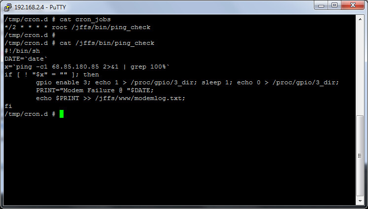
I also created a simple ping script and a cron job which ran every 2 minutes, pinging a comcast gateway (it was the first IP address out side the modem I hit when I ran a trace route)
And finally, the finished product in use! (this was an earlier revision, when the relay was still being housed in the peanut butter jar) You can see the Fonera and the outlet box with the modem's wall-wort to the right of the printer.
(Click the image for a larger version)

All in all, this was a very fun project and it seems to do it's job very nicely. The only time we experience any problems now is when the cable line is so noisy that the modem takes more than two minutes to re-sync, and goes through a couple resets before it's good again.
I hope this information can help someone else build a similar device to fix a similar problem (I know there are lots of frustrated comcast customers out there that this project might help). If you come across something in my write up that doesn't make sense, or needs clarification, leave a comment or otherwise contact me and I'll try to help you out as best I can.
Happy Hacking!
I once considered this although I never considered doing it from a router. I was going to rig up a smart outlet (ie outlet with a relay capable of being controlled by a microcontroller) and a ZigBee network.
ReplyDeleteThen I found that I could reset the modem remotely by going to 192.168.100.1, and choosing restart modem from there. I don't know if either of these would work wth your solution just trying to offer some ideas.
Could you say what transistor you used in the fonera?
ReplyDeletedoes your script delete the log when it gets too big?
i like this, its clean nice and completely hardware, no matter the fault, it will hard reboot it.
ReplyDeletethat said, as steve mentioned, you could also make a software only system using curl (install on fonera).
http://www.autohotkey.com/forum/topic32052.html
this assumes that the modem management http server stays up during the issue.
It looks like his schematic is wrong. Schematic shows that you are connecting the collector of an NPN transistor to ground instead of emitter. It either needs to be a PNP transistor or the 3.3V and ground lines needs to be switched around.
ReplyDeleteNice hack. However where'd you obtain the Fon gizmo? Also is the code available? It might be possible to add this feature to other routers who support DD-WRT.
ReplyDeleteAlso two other things, one is that you might want to check your schematic, there are comments that the transistor position is incorrect versus the relay, of course if it did work for you then they are wrong. The other thing concerns those characters at Comcast. I suggest that you keep bothering them to check something near your connection. If your connection is part of a block of ones that works, then perhaps the cable line feeding it is acting up. If there are others with similar problems then not surprisingly Comcast needs to make a service call to all of them. There are specific cases regarding why Comcast can be a bit dense regarding persistent problems. E-mail me off board if you're curious please. Also concerning a code drop.
@stevefrmnj: I was actually not aware that the modem had a software reset function, but I wanted a hardware solution anyway as the modem was hard-locking in a fashion I had never seen before. This particular modem was a Scientific-Atlanta model.
ReplyDelete@bbsux: The transistor is a Motorola SN3053,A. I had it around, still in it's Radio Shack "Archer" packaging. I do not have a function in my script to chop the log when it gets to large, although that would be pretty simple to add.
@ConcinoS: Looks like I did mess up the diagram. :P I drew it from memory well after I had actually created the circuit. I'll swap the picture out with a corrected one. Thanks for the correction!
@Gregg: I got the Fonera a few years ago when they were giving them away for free. You can still buy them from their website. I have since moved out of that apartment, but while I lived there, I called Comcast at least once a week for months. They sent numerous technicians out, all who were baffled by the problem and amazed at my roommate's and my knowledge of networking and electronics (they also loved my Mountain Dew Christmas tree, which you can see in an earlier blog post). They replaced our modem at least 3 times, all of them experiencing the same issue. One brought a spectrum analyzer which showed a large spike smack in the middle of the frequency band every few seconds. He guessed that it was probably this strange signal that was confusing and knocking the modem offline. They checked the signal coming into the building and were shocked at how strong it was. They guessed that the problem was most likely some bad wiring within the apartment walls somewhere (everything we could see was RG-59), but that was apparently not Comcast's responsibility, it was the landlords. Needless to say, the landlords didn't do squat about it which was why I created this device. Problem solved :D (sorta)
P.S. @Gregg: as far as the code I used, I posted a screenshot of the cron job I used and the code in the script that cron runs. Everything else is included in the standard DD-WRT build. The only thing I didn't post was the html code for the interface, but you should be able to figure that out ;)
ReplyDeleteI'd also like to get the interface.. I tried to setup the one in the dd-wrt wiki for the gpio and couldn't get it to work
ReplyDeleteOut of curiosity, what type of relay did you use in this?
ReplyDeleteif you don't want to burn your house down, just get a christmas light timer and put the on off pins next to each to go off and back on in the middle of the night
ReplyDeleteHow did you hack the Fon router? I have two, and have tried to DDWRT them both, and failed. Do you have a link with instructions?
ReplyDeleteThanks
Rick
Omar: Why do you think He will burn his house down? It looks perfectly fine to me in terms of electrical codes. He's switching the black (hot) on/off which is correct. He's isolated the Low voltage (the signal to turn the relay on and off) from the high voltage.
ReplyDeleteRick: I had to use the serial method to install dd-wrt on my fon's, you don't have to mess with the tftp server stuff.
BTW I'd still like to see the html code for the interface.
Thanks
Fonera Automated Reset Technology
ReplyDeleteNice acronym there!
Ok, for the web interface it's kinda funky. First I enabled the /jffs partition via the DD-WRT web interface. Then I followed this guide: http://www.dd-wrt.com/wiki/index.php/WEB_server
ReplyDeleteThen I created the actual web pages, which you can see the contents of here: http://pastebin.com/azdrc0u0
@Jake: I got the relay from Fry's Electronics. Here is a picture of the packaging, with all the info you should want http://farm5.static.flickr.com/4095/4750131967_d4a6bca5d0.jpg
@Rick: I hacked my Fonera(s) several years ago using the built-in RedBoot boot loader. There are instructions on DD-WRT's website, as well as many other sites with detailed instructions on how to hack your Fon.
@Golben: I'm glad somebody caught that ;)
Thanks... I may even modify it a little to give on/off control to the other GPIOs with solid state relays.
ReplyDeleteBTW why didn't you use a solid state relay? I bet the gpio would output enough current to run it directly.
They aren't too expensive used from ebay...
Can you please give me your email address. I am trying to make a similar setup on Linksys WRTSL54GS running Tomato 1.27 VPN.
ReplyDeleteI have some questions about the script used and how to improve it further for specific scenarios.
Your help would be appreciated.
Please email me on hyper.escape@gmail.com
Alterego: There are 2 free GPIO on the wrtsl54gs
ReplyDeleteGPIO 5 OUTPUT SES LED (Cisco white LED)
GPIO 7 OUTPUT SES LED (Cisco amber LED)
I don't have mine runnin g right now but the only downside I can see is if they blink during boot.
Gigawatts: Is there a way to modify your script to not only check if its is getting a ping back BUT also reboot if the ping is too high?
ReplyDeleteThe longer my road runner stays on without a reboot the higher the ping times get it seems.
Yeah, that shouldn't be too difficult if you know how to do some simple shell scripting. I am just checking to see how many packets were lost, and if its 100%, it toggles. You could modify it to activate under any circumstance you want.
ReplyDelete@bbsux: I didn't use a Solid state relay because I could not easily find one cheap. The one I bought from Fry's was like $3, and I had all the transistors I needed. If you have a cheap source for Solid State relays, let me know, I would love to get a couple!
ReplyDeletecan you please list the specs of all parts ?
ReplyDelete1 x Fonera 2100 Router (could probably use anything with GPIO pins you can control)
Delete1 x 3 volt relay (anything with the right coil voltage will do) with a basic diode across the coil
1 x NPN transistor (again, generic, anything that can source the current your relay uses will be fine)
1 x Chopped up extension cord (or you could use a wall outlet and single gang box like I did)
If you use a Solid state relay instead, you may be able to skip usage of the transistor. Just measure how much current your relay uses, and decide from there.
Thanks for the list. i have the router and wire, can you please give an examples of relay (I will probably try with regular relay first, not solid state), diode and NPN transistor spec. Sorry I am a noob and don't want to get something which can't handle the voltage from other part.
ReplyDeleteBEEN a long time since someone wrote something, but SOMEONE has to note that he did his programming with a straight: cat few_dare_this.fileext
ReplyDeleteMeow!
ReplyDelete